Arduino I2C communication
While developing my energy monitoring system and my flood control system I decided I wanted to integrate the two in order to be able to monitor the flood control system using one of the sensor nodes of the energy monitor system.
The reasons behind it were:


The relevant parts are the following:
For the master I am not using the standard Wire library from arduino, but a modified library that has more flexibility in handling timeouts and in general transmission problems:
Arduino I2C Master Library
Using this library I am able to set a timeout for executing I2C commands in setup(): functions will return an error code that can be checked for successful completion (an example in loop() is the call to I2c.read).
The relevant part in the loop() function checks whether the slave is present and, if so, requests the data and stores it in a structure that will later be transmitted to the collecting node
And this is the code for the slave
Loading ....
The relevant parts of the code for the slave:
What happens is that every five seconds the sensor node asks for the data to the rboard node, stores it in the sensor payload and forwards it to the logging station together with the sensor data.
Things I am monitoring:
The reasons behind it were:
- The sensor node doing the monitoring was already physically near the flood control node
- The flood control node has support for wireless modules (nRf24) but it is a different technology from what the open energy monitor nodes use (rfm12b)
- The need to be able to monitor the state of the float switches, the manual override switch (it is in a kids safe area, but not in a 'don't know what this is for, let's try and see' area ...)
- I wanted to experiment with I2C communications
I2C is a multimaster serial single-ended computer bus invented by Philips used for attaching low-speed peripherals to a motherboard, embedded system, cellphone, or other electronic device.
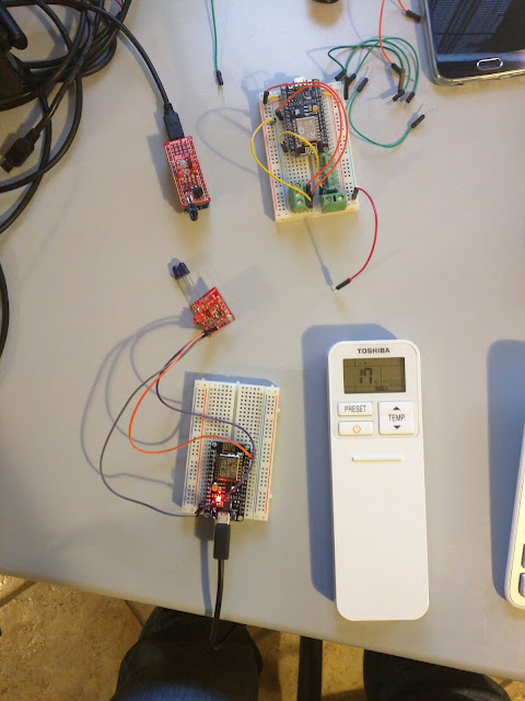
In particular I needed to exchange data between an emonTx node:
and an rboard:
Both boards expose the standard pins used for arduino I2C communications:
- A4 (SDA) on the rboard is labeled AD4, on the emontx SDA
- A5 (SDL) on the rboard is labeled AD5, on the emontx SDL
Phisical connection is a matter of connecting two GROUNDS, SDA to SDA and SDL to SDL on the two units.
Once the hardware had been taken care of I had to consider how I wanted communication to flow.
The I2C bus is shared between potentially lots of devices hence there is the need to handle communications by electing a master that controls who is going to use the bus and a slave that server the data when requested. I elected the master to be my emontx unit and the slave to be the relay board, this way it was trivial to insert the data request code in the emontx firmware, that collects the data when needed, adds it to the data already collected from its sensors and transmits it to the collecting node, adding some checks for anomalies.
This is the code for the master:
Loading ....
The relevant parts are the following:
 #include <I2C.h>
 ....
 void setup()
 {
  I2c.begin();
  I2c.pullup(true);
  I2c.timeOut(2000);
 ....
 void loop()
 {
 ...
 // Request data from slave.
  uint8_t r = I2c.read(SlaveDeviceId,(uint8_t)6);
  if (r==0){
   if(I2c.available() ==6){
    emontx.sw1State = I2c.receive() ;
    emontx.sw2State = I2c.receive();
    emontx.sw3State = I2c.receive();
    emontx.pump1Active = I2c.receive();
    emontx.pump2Active = I2c.receive();
    emontx.anomaly = I2c.receive();
    if (emontx.pump1Active && emontx.power1 < 100){
     emontx.anomalyRelay1 = 1;
    }else{
     emontx.anomalyRelay1 = 0;
    }
    if (emontx.pump2Active && emontx.power2 < 100){
     emontx.anomalyRelay2 = 1;
    }else{
     emontx.anomalyRelay2 = 0;
    }
    digitalWrite(LEDpin, HIGH); delay(20); digitalWrite(LEDpin, LOW);   // flash LED
    delay(200);
    digitalWrite(LEDpin, HIGH); delay(20); digitalWrite(LEDpin, LOW);   // flash LED
    Serial.print("Switch 1: ");
    Serial.println(emontx.sw1State); delay(100);
    Serial.print("Switch 2: ");
    Serial.println(emontx.sw2State); delay(100);
    Serial.print("Switch 3: ");
    Serial.println(emontx.sw3State); delay(100);
    Serial.print("Pump1: ");
    Serial.println(emontx.pump1Active); delay(100);
    Serial.print("Pump2: ");
    Serial.println(emontx.pump2Active); delay(100);
    Serial.print("Pump1 Anomaly : ");
    Serial.println(emontx.anomalyRelay1); delay(100);
    Serial.print("Pump2 Anomaly : ");
    Serial.println(emontx.anomalyRelay2); delay(100);
   }
   else
   {
    Serial.print("Unexpected number of bytes received: ");
    Serial.println(I2c.available());
    emontx.sw1State = -1 ;
    emontx.sw2State = -1;
    emontx.sw3State = -1;
    emontx.pump1Active = -1;
    emontx.pump2Active = -1;
    emontx.anomaly = -1;
    emontx.anomalyRelay1 = -1;
    emontx.anomalyRelay2 = -1;
   }
  }else{
    Serial.println("Slave not connected!!!");
    emontx.sw1State = -1 ;
    emontx.sw2State = -1;
    emontx.sw3State = -1;
    emontx.pump1Active = -1;
    emontx.pump2Active = -1;
    emontx.anomaly = -1;
    emontx.anomalyRelay1 = -1;
    emontx.anomalyRelay2 = -1;
  }
 ....
For the master I am not using the standard Wire library from arduino, but a modified library that has more flexibility in handling timeouts and in general transmission problems:
Arduino I2C Master Library
Using this library I am able to set a timeout for executing I2C commands in setup(): functions will return an error code that can be checked for successful completion (an example in loop() is the call to I2c.read).
The relevant part in the loop() function checks whether the slave is present and, if so, requests the data and stores it in a structure that will later be transmitted to the collecting node
And this is the code for the slave
Loading ....
 #include <Wire.h>
 ...
 void requestCallback()
 {
  uint8_t buffer[6];
  buffer[0] = sw1State;
  buffer[1] = sw2State;
  buffer[2] = sw3State;
  buffer[3] = pump1Active;
  buffer[4] = pump2Active;
  buffer[5] = anomaly;
  Wire.write(buffer, 6);
  blink();
 }
 void setup() {
 ...
  //I2c Init
  digitalWrite(A4, HIGH);
  digitalWrite(A5, HIGH);
  Wire.begin(SlaveDeviceId);
  Wire.onRequest(requestCallback);
 }
What happens is that every five seconds the sensor node asks for the data to the rboard node, stores it in the sensor payload and forwards it to the logging station together with the sensor data.
Things I am monitoring:
- Switch states (I have a low level, high level and manual intervention switch)
- Pump activity (I have two pumps)
- Anomalies defined as either high level switch being on and low level off, or pumps being reported as active but no corresponding current flow being detected
I used a different version of the I2C library on the master because with the standard Wire.h situations like the sensor node being powered on and the rboard being powered off and the I2C bus connected would cause the master to hang (and the watchdog to kick in and reset the board) and I didn't want the rboard to act as master


Commenti
Posta un commento