Arduino Relay Board to drive two flood pumps
This means that when it does rain the street in front of the house get like this:
and that the area in front of my garage (and my garage and basement) get like this:
in the years I have worked to avoid this from happening but it has always been a trial and error process where when in error I get to work half a day cleaning the mess up.
Things I have tried:
- Modify access to the street so that excess water stays in the street
- Add one (and later a backup) sump pump in a drain that collect water when the main drains aren't working. Each pump has a float switch and the switches have given me nothing but grief (sometimes they get tangled, sometimes they get almost up but they don't start)
- Try to understand when this happens other than being there, looking outside and doing some rough calculations that get forgotten one week later ...
In order to collect and be able to analyze data I merged two projects:
- Open Energy Monitor allows me to monitor home energy usage in general, and pump activation in particular
- Sint Wind Pi allows me to gather meteo data from my backyard sensors, and correlate them with pump activation
This is an example of when things work:
Today we had a little shower that landed about 10mm of water in about 10 minutes. This is usually enough to overload the drain (it looks like a small amount, but in such a short time it really is a lot of water ...).
This is the data that was logged from the weather station:
and this is a log from the energy monitoring system:
What happened is that the main drains overloaded, and pump number 1 kicked in and only needed help from pump number 2 for a short time before the rain slowed down and then eventually stopped.
This is an example of things not going according to plan:
in june we had another 'little' shower going on that in about 30 minutes poured down about 35mm of water
and this is a log from the energy monitor:
What happened is that pump1 kicked in as expected but (I discovered it later) was not working properly because of leafs and other stuff blocking it, while pump2 never switched on (and it would probably have saved the day ..). The activation of pump2 was me opening the drain and putting my hand down and forcing the switch to come up and stay up, but it was already too late and I had my garage with abour 5 cm of water in it ....
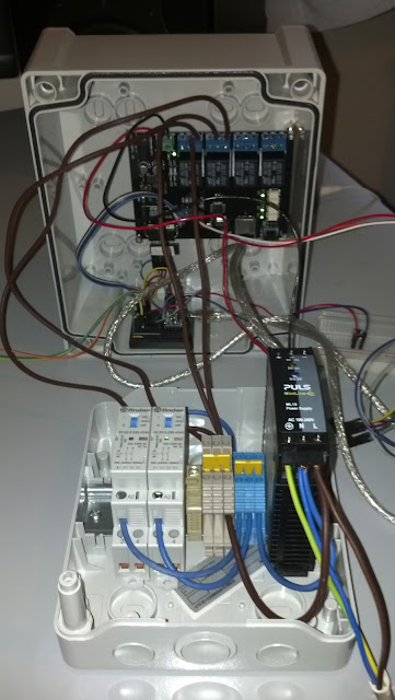
So I decided to step up to the challenge and (as long as power doesn't go out) I have come up with this little arduino hack:
- Two float switches that will be placed in the drain where the pumps are and will measure min water level and max water level. Eventually I will add two more to avoid failures
- One Arduino duemilanove board called Rboard that is able to drive four relays (at the moment only two are used) and has enough input left to handle monitoring the switches (and sending data to another arduino via I2C or wireless, if needed)
- Two Finder contactors that will actually drive the pumps since I discovered that driving a motor in general requires special hardware in order not to have sparks flying and electronics go down in smoke
The new plan is something like this:
- Have the Rboard monitor water level through the two switches and, if needed, switch on the two pumps: one at first and the second shortly after if water level doesn't get back to normal
- Have an additonal 'emergency switch' to turn on the pumps without having to open the drain and put my hands inside
- Monitor switch state through I2C to another arduino (the one collecting energy data) and into my energy monitoring system. This will allow me to raise alarms if some anomaly (upper switch on and lower off, for example) present themselves
The two float switches are connected to analog input A0 and A1 on the board, the emergency switch to A2.
A3 is used to drive a led that is normally off, blinks during I2C comms and stays on when the emergency switch is on to indicate the state.
A4 and A5 are used for I2C comms.
A4 and A5 are used for I2C comms.
This is the code:
Loading ....


Commenti
Posta un commento